‘taxi-in-a-box’
Sometimes referred to as “taxi-in-a-box”, VDS3 is not only the most compact taxi solution in the world but also the most versatile and extensive one that boasts features other systems cannot provide.
It encompass a wide range of functions (metering, dispatch, navigation, payment, security camera operation, vehicle management, driver management, and many more) and can be deployed in taxis, emergency services, patient transport, rideshare vehicles, delivery vehicles, trucks and buses.
VDS3 not only meets the mandatory requirements of state regulators but excels with so many class leading features in one incredibly compact turn-key solution. VDS stands for Vehicle Dispatch System and the 3 indicates the 3rd generation status.
Net-Cabs has field deployed VDS3 in over one thousand vehicles of varying makes and models. The device has been exposed to the harshest environmental conditions in Australia and tested with the widest range of vehicles, ranging from combustion engines to hybrid to electric ones and from sedans to vans and buses. By feeding results from each hardware and software iteration back into R&D, Net-Cabs has been able to enforce a rigorous hardware and software improvement process that ultimately results in a robust solution.
The functional and non-functional capabilities of VDS3 ensure it stands uniquely apart from other systems. For instance, the typical taxi equipment installation process in Australia takes two technicians between 6 and 8 hours (including installation of a mandatory security camera system). VDS3 can be installed by one technician in under 3 hours, including security cameras.
The reason for this is that contemporary systems rely on several devices to fulfill mandatory taxi functions. With VDS3, only a small controller needs to be installed and a head-unit to be mounted, and apart from battery power and ignition feeds, everything else is simply plug and play (such as camera-heads and OBD).
Managing VDS3 (or a fleet of them) is simple as the system is self-configuring (fares, vehicle, driver), self-calibrating (meter), self-monitoring (health-checker) and self-healing (system recovery).
Fully Approved Extensive Integrated Features
The VDS3 system has received all regulatory approvals in Australia. Considering that VDS3 performs the functions of several purpose-built devices, Net-Cabs decided to use aliases to help the regulator align its segregated approval process with a given VDS3 configuration.
For instance, the meter is referred to as VDS meter or Oiii® meter by the legislator whilst the security camera system is referred to as OiiiCam®. In reality however, it is the same system.
The meter is the VDS3 controller with the head-unit attached, and OiiiCam is the controller with its camera-heads plugged in. VDS3 can be installed in a taxi with camera-heads and head-unit (meter, dispatch and security camera operation), whilst a rideshare car may only require OiiiCam (controller and camera-heads for security camera operation).
VDS3 does not operate in isolation; it is part of an overarching system operations platform that incorporates managing fleets of taxi operators, vehicles and drivers whilst providing safety management, navigation, payments, fund distribution, passengers, job bookings and dispatch, security cameras, disability and government levies, auto-tolling, distress calls, video calling and more.
In addition, Net-Cabs provides a comprehensive role based administration portal, innovative driver and passenger apps, a job auction platform where passengers can negotiate with drivers in real-time (OiiiBid®), and a facility where drivers can set up their own dispatch network to offload jobs amongst friends and earn commissions in the process.
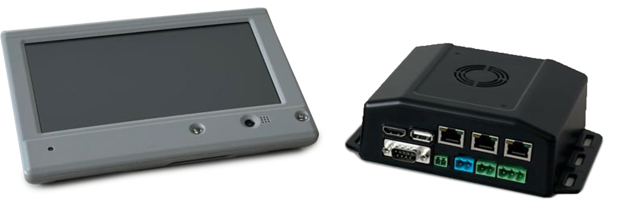
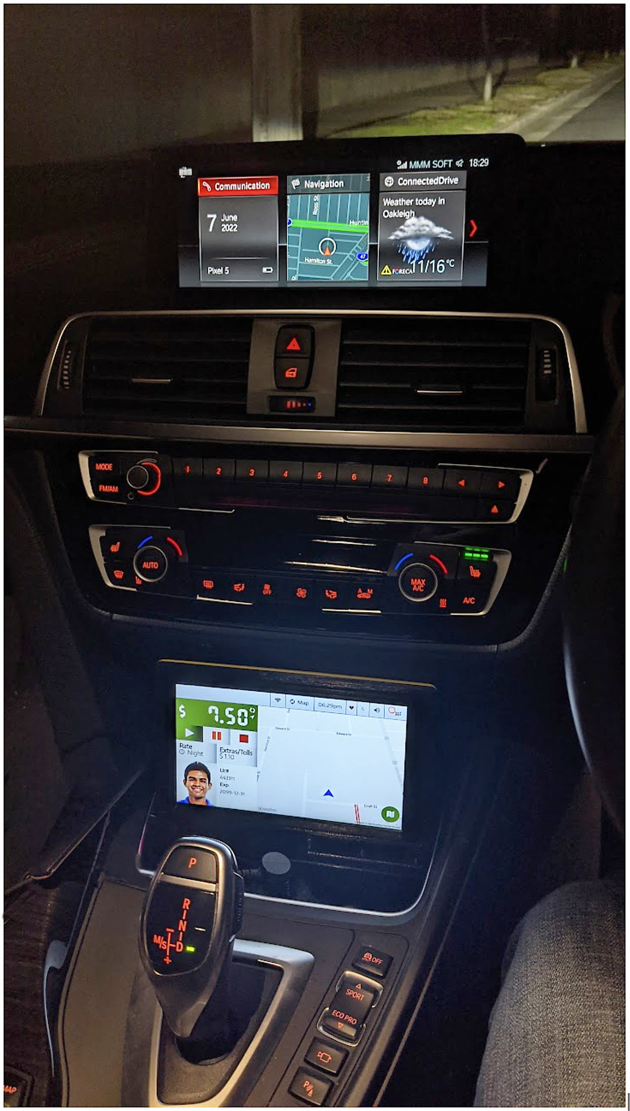
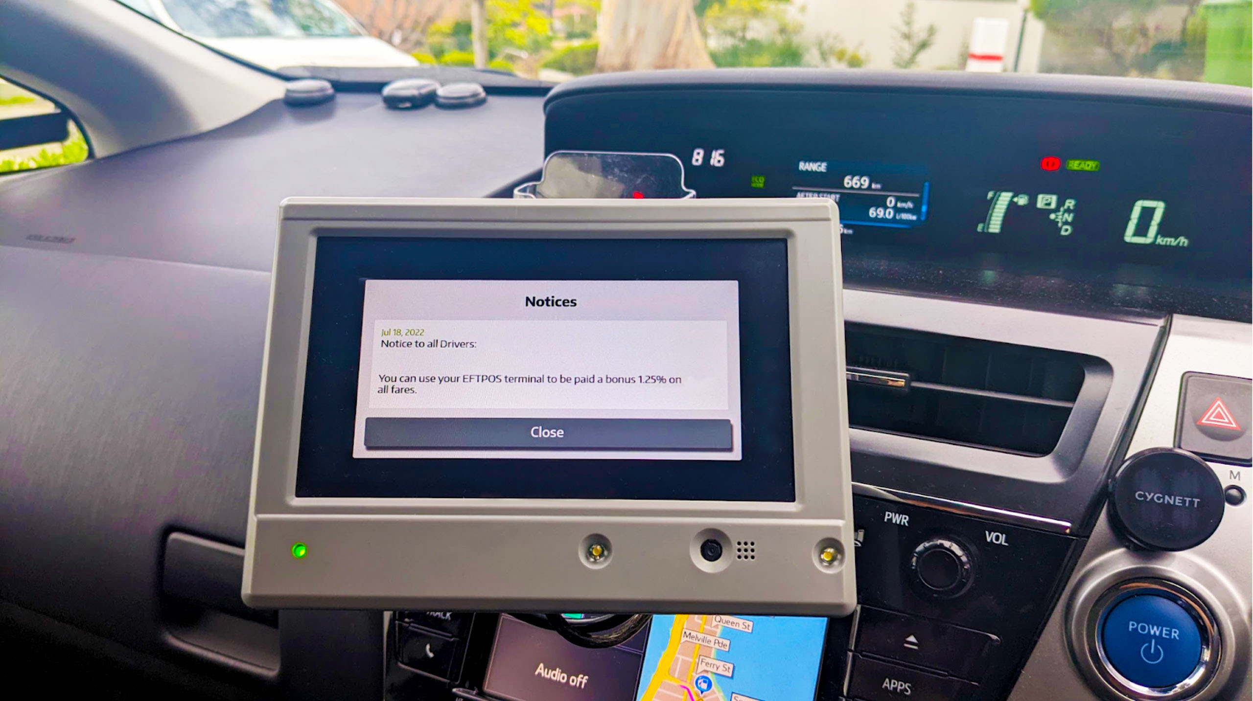
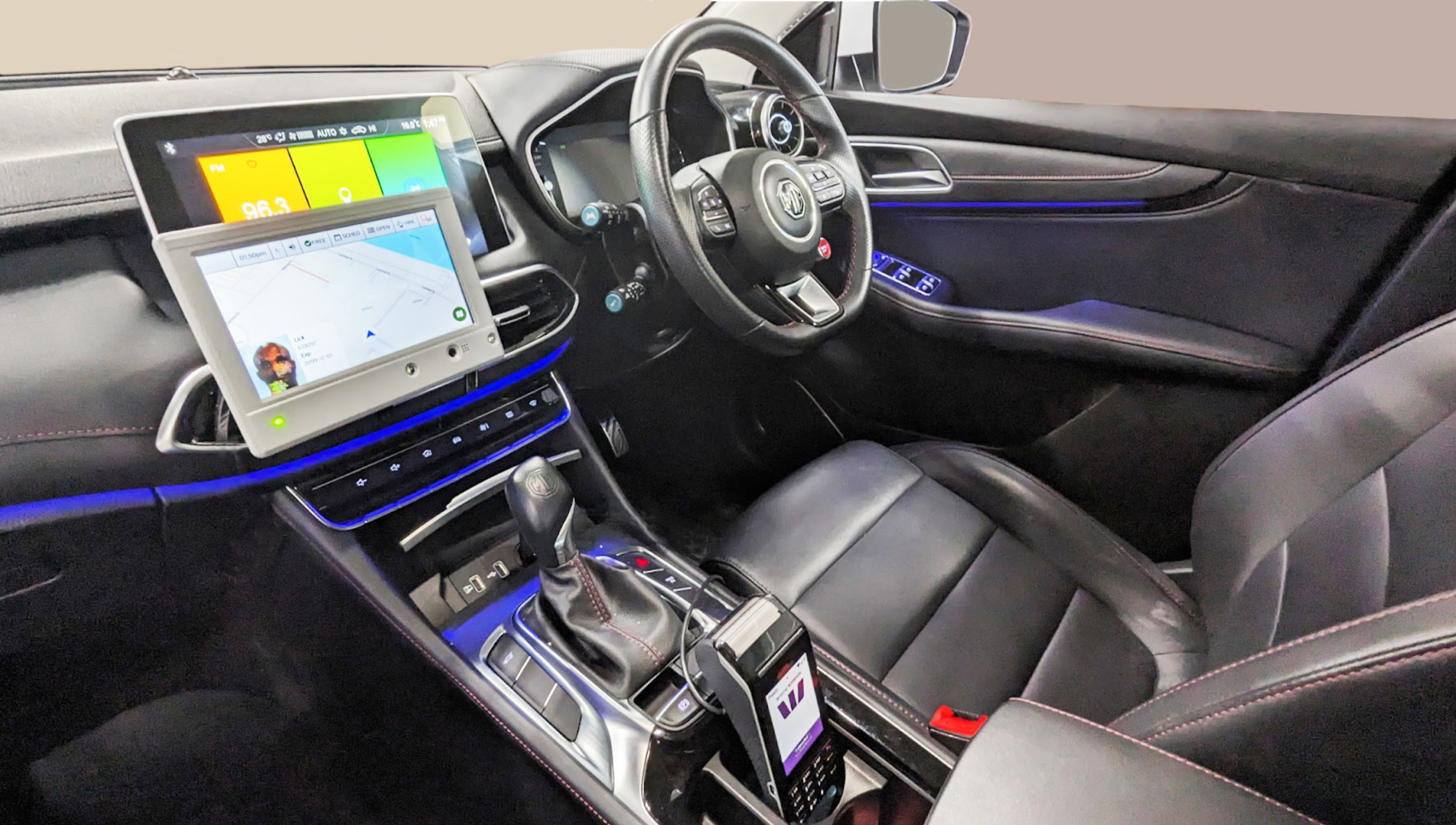
Net-Cabs VDS3 Head Unit & Controller
System
The key system components of VDS3 are a controller, a head-unit and one or more camera-heads. Peripherals include antennas, an OBD cable and a payment terminal.
The controller facilitates all computational and storage functions. It provides all head-unit controls, security camera operations, power control, watchdog functions, RTC control, ODB functions, domelight control, data and location services, numerous input/output controls, wifi access point control, remote access and over-the-air updates.
The head-unit provides the in-vehicle driver and passenger interface and performs various other functions including speaker output, webcam, card scanner, distress button, video calling, status LED, flash LEDs, antenna sockets (2 x LTE antennas and 1 GPS antenna) and a reset button.
The camera-heads plug into the controller and are managed by it. Camera-heads can be configured to provide internal cabin footage, road facing footage and side views (e.g. mounted as a roof camera to provide driver or passenger side views of the street).
Subject to the controller model (see below), LTE and GPS antennas can be connected to the head-unit or the controller.
Models
At the heart of VDS3 is the controller. It is the brain of the in-vehicle system running on an ARM-based processor with custom firmware.
Every aspect of the hardware and software has been optimised for its function, designed to perform in any vehicle and under a multitude of operational settings.
The electronics design has meticulously evolved to address all short-comings of previous generations. The software has been developed to provide low level component control whilst supporting the ability to add new features quickly without impacting the controller’s core functionality.
The controller is available in two base models – FL and HL.
VDS3 Models
| Model | Differences | Benefits | Use cases |
|---|---|---|---|
| FL (full operation) |
Requires a head-unit to operate | Takes advantage of the features and benefits associated with head-unit operation | Full-taxi operation |
| HL (headless operation) |
No provision to attach a head-unit | Modem is built into the controller | Camera-only operation (head-unit is not required for operation) |
Port Configurations
| Interface Type | VDS3 (FL) | VDS3 (HL) |
|---|---|---|
| HDMI socket for driving the head-unit display | ||
| USB socket for driving the head-unit components (USB and serial devices) | ||
| DC socket for supplying power to the head-unit | ||
| OBD Socket for ECU communication | ||
| Domelight socket for controlling the taxi dome light | ||
| LED socket for controlling the camera status | ||
| Button socket connector to provide an optional physical distress button that can be hidden (the head-unit also provides a distress button on the interface) | ||
| Ports for camera-heads | ||
| LTE Antenna sockets | ||
| GPS Antenna socket | ||
| WiFi Access Point |
Configuration
Every aspect of VDS3 can be configured remotely including the driver user interface which can be controlled remotely in real-time.
There are two key groups of users that configure the VDS3 system – system administrators and installers.
System administrators can run remote execution scripts from the admin portal on one or more VDS3 devices or log on to a specific device over a secure connection to edit configuration files and execute operating system commands.
System updates occur over the air and are fully automated. Every system update arrives with its own configuration file named vehicle_server.yml. As new features become available, vehicle_server.yml will typically contain an extended set of configuration parameters.
To retain device specific settings after an update, an administrator’s set config.yml is persistent. VDS3 parses the vehicle_server.yml file and then applies the config.yml parameters over the top.
System administrators usually define a subset of parameters in config.yml that are specific to a given VDS3 deployment. For instance, they could specify the backend environment VDS3 must connect to, what maps should be used, what camera configuration should be applied, who the acquirer of payment terminal transactions is and so forth. Any default configuration parameters defined in vehicle_server.yml are overwritten by the custom config.yml file.
Installers predominantly use the VDS3 setup menu and the device management function of the Net-Cabs admin portal to complete a vehicle installation. It typically involves three key tasks: 1. linking and activating a VDS3 device, 2. pairing the payment terminal with VDS3 and 3. ensuring the camera-heads have been correctly mounted.
In task 1 as noted above, the installer requires portal access (role based access for a given operator) to generate a key for a specific VDS3 device ID.
If portal access is granted, the installer is provided with a short lived token (a 4 digit number) which must be entered into the VDS3 setup menu on the head-unit mounted inside the vehicle. If the token matches and the key exchange is successful, the VDS3 device is linked to the vehicle.
From then on, the device will be sending its operational metrics to the Net-Cabs’ backend which can be viewed in real time in the admin portal.
The process for task 2 is also straightforward. The payment terminal connects to the Wifi access point built into VDS3 and after a pairing process, it begins communicating with the controller.
Task 3 is used to validate that the camera-heads have the correct field of view. The installer is able to see the camera views on the head-unit and make mounting adjustments as required.
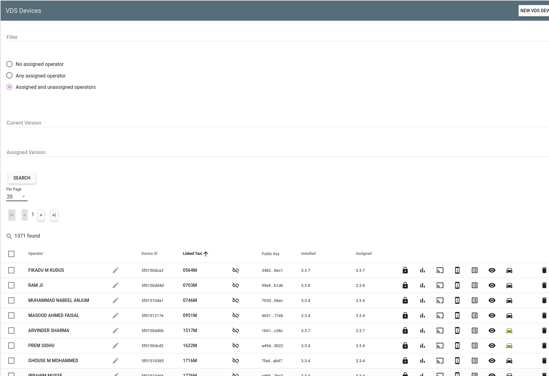
Management
The Net-Cabs Admin portal provides comprehensive capabilities to manage VDS3 devices. The system facilitates streamlined version control, remote access functionality, script customisation and its remote execution, access to real-time device statistics and problem reporting and diagnostics.
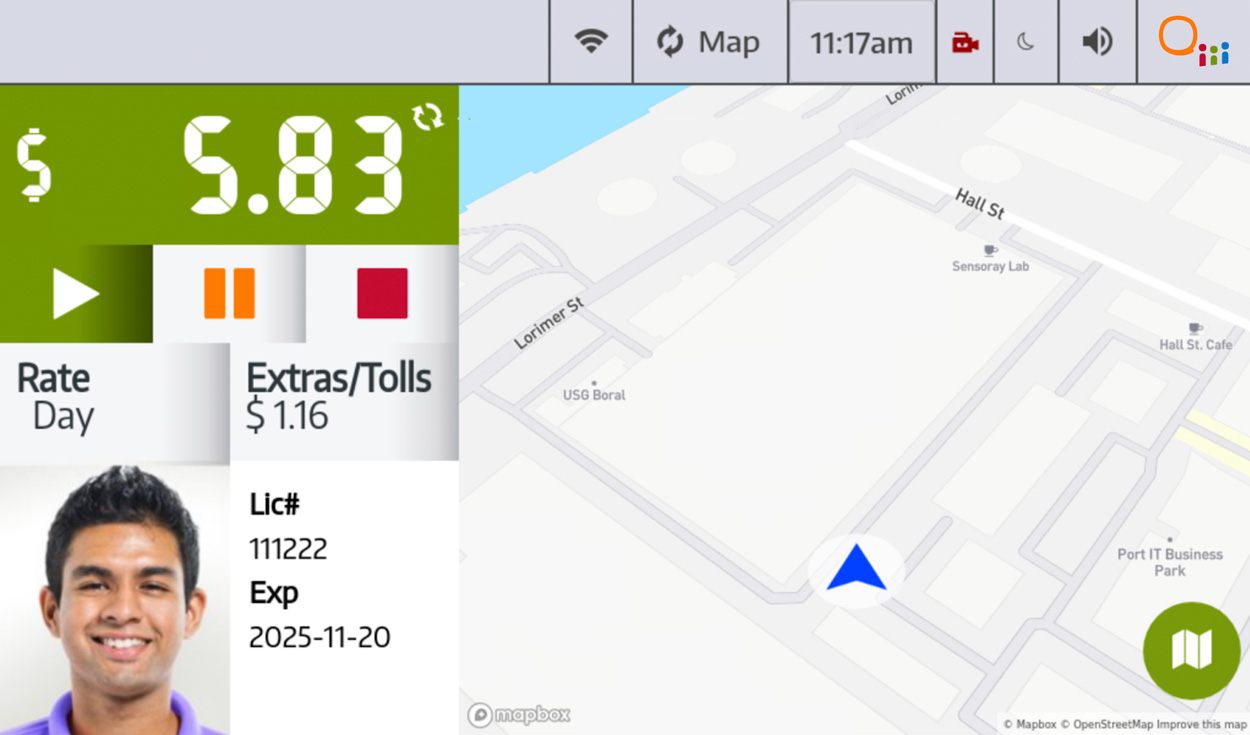
Viewing the VDS screen:
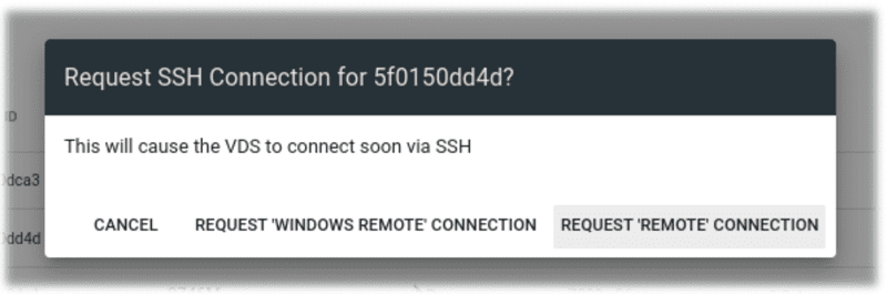
Requesting remote access:
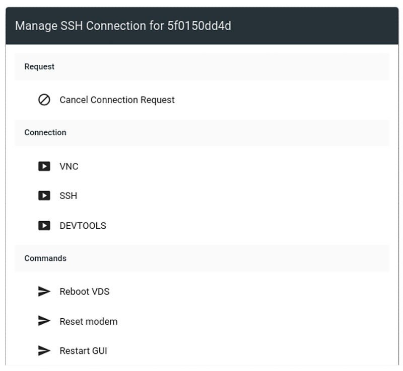
Choose connection method or execute custom scripts remotely:
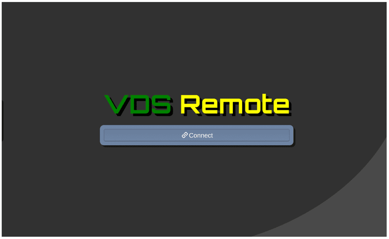
VDS Remote Connect Screen:
VNC session to UI on the VDS3 head-unit. Mounted in Vehicle:
Viewing VDS3 Problem Diagnostics:

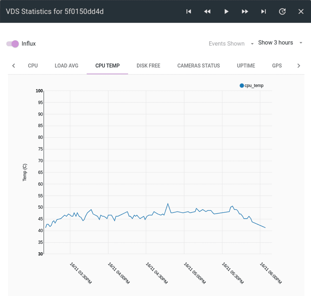
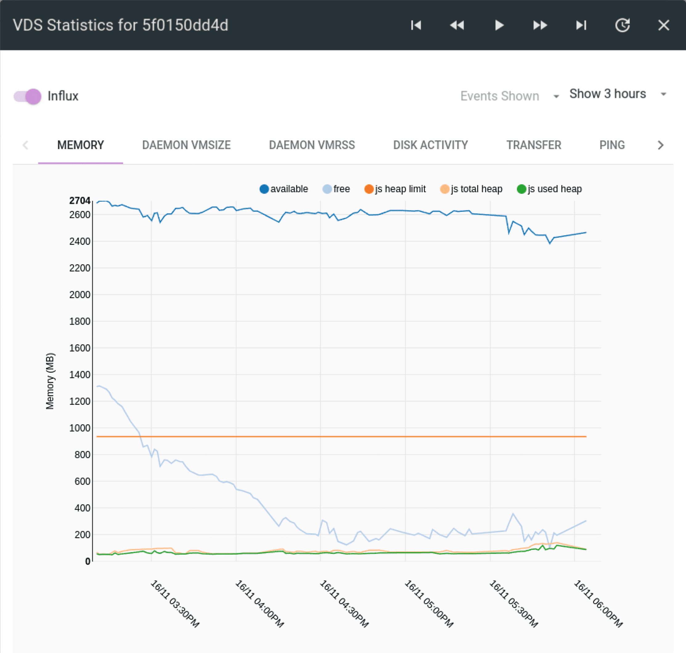
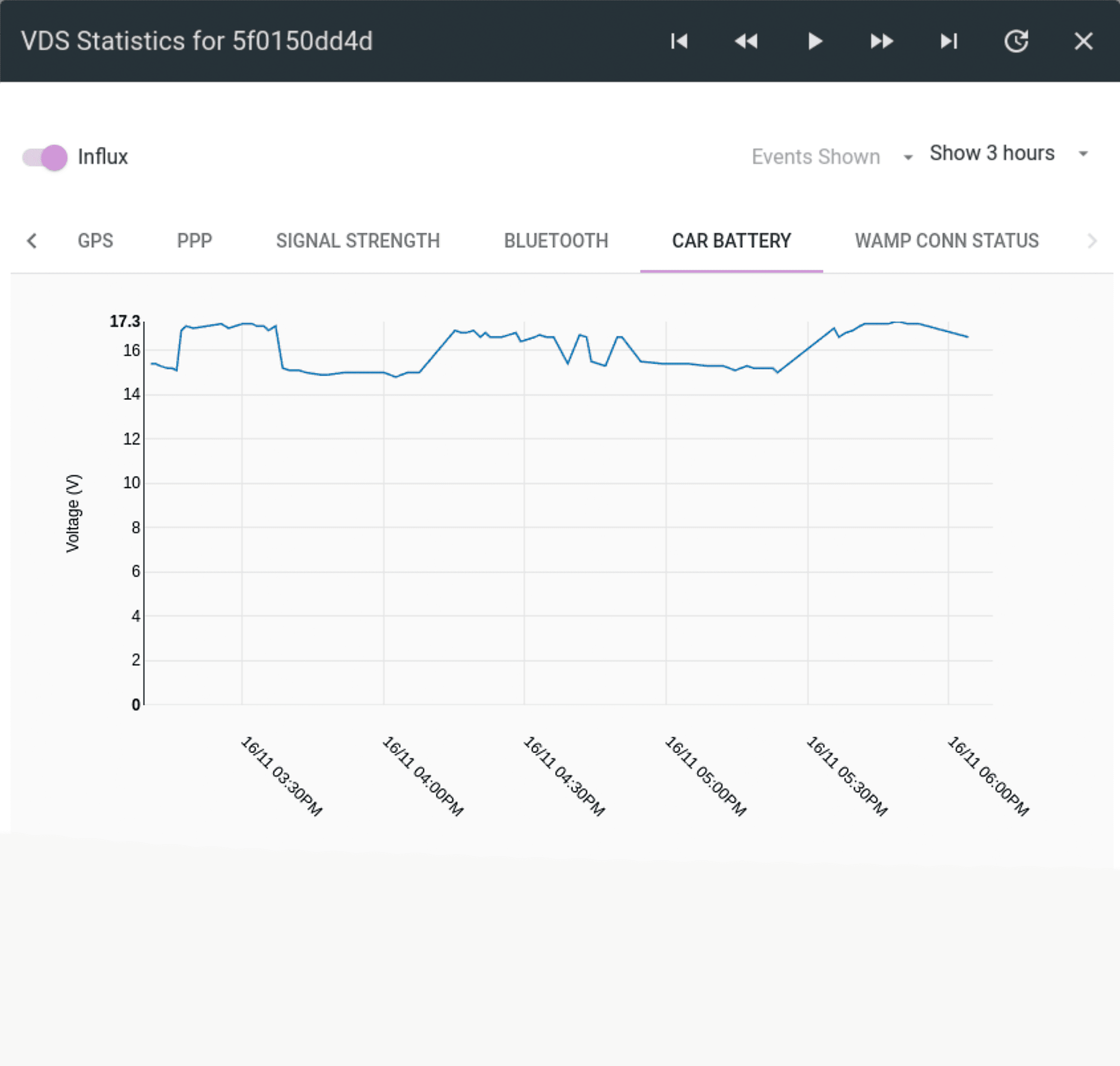
Checking VDS3 stats.